
SUMMARY
Omega Rubber Heaters
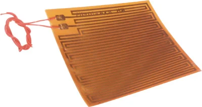
This week we finalized our hardware specifications and ordered our heater from Omega Engineering. We decided to get two 3x3" silicone rubber heaters, each with a power density of 10 W/in^2. These heaters take an input of 110V, so we shouldn’t have any trouble connecting them to existing power infrastructure in Hesse Hall. The heaters were chosen based on the size of the shock body, the heat input required, and Omega’s current stock. Although there were some heater sizes that may have more perfectly suited our needs, any out of stock heater would require a five week lead time, which is much too long to wait at this stage in the project. By next Tuesday we should have all the necessary hardware - a heater from Omega Engineering, a solid state relay from Alex, and a microcontroller from Eric. With these materials, we should be prepared to assemble our entire project, barring the completion of modeling and simulation.
Advances in the software have also been made. We now have a successful parameter identification method/code that can be used to characterize future, more complex models. Our original model has already been characterized using the method and previously taken data. With all of our hardware purchased and a method for characterizing that hardware, we have a much better idea of how to implement our controller. Deciding which tests to run, so that we can accurately characterize our system and our model, will be key, especially since our lab time is limited. We believe we are on track with both the hardware and software design, and we are excited to begin verifying our designs
Thanks for reading!
-The Hot Shocks
INDIVIDUAL THOUGHTS
GRACE
This week, we focused as a group on purchasing the hardware necessary for the shock. It was crucial that we buy the heater this week so that next week we can begin constructing our project. We ended up deciding to use a flexible silicone rubber heater, because it fits our specs in terms of power density and dimensions and it was in stock. After looking at the datasheet and manual for the part, I decided to also make a list of possible hazards we should monitor to assure the safety of our team and the heater.
- Maximum operating temperature (232C): Though we cannot monitor this temperature directly, it would be best to make sure that the oil temperature does not reach half of the max operating temperature to assure that the heater is well within its safe range.
- Heater attachment: In attaching the heater to the shock, we must be sure to prevent any air pockets from existing between the shock and the heater, otherwise we may have heater failure. To assure this, it will probably be necessary for two people to install the heater: one to hold it in contact with the shock, and one to clamp it down.
- Maximum bending radius (2 in.): The maximum bending radius of the heater is 2 in, and the shock is about 1.5 inches in radius. This may pose a difficulty in attaching the heater, and we will need to assess the situation more thoroughly once we receive the heater.
TURNER
Early this week, after estimating the required heat input from the specifications of the dyno motor, I spent a lot of time on omega.com looking at all of their different options for heaters. Once Christy, Grace, and I narrowed our choices to flexible heating blankets and flexible silicon rubber heaters, we had to decide on the correct size and power density for our desired heater. After accounting for cost and the Omega’s current stock, we decided to go with the flexible silicon rubber heaters. I ordered the heaters described in the summary on Tuesday afternoon with three day shipping, and they should be arriving at my apartment by Monday. The plan for this weekend is to help Les further refine his plant model by finding a more accurate value for the overall heat transfer coefficient as a function of RPM. Once the model is complete, we will be able to simulate the system just in time to start assembling hardware.
LES
I finished developing the controller models for the heater. Working with Grace, Turner, and Christy, I implemented the properties of the heaters in the model and was able to get a good estimate of engine’s energy generation and of the convective cooling coefficient of the system. The plant model is now accurate for a limited set of operating conditions, and with the parameter fits Justin and Eric developed, we should be able to accurately model the shock for any setup we want to test. I solved the error saturation problem I was having in the PID controller by mapping the output of the controller to the Arduino’s AnalogWrite method, and then saturating that argument after it was mapped. I then compared the transient characteristics of both controllers in terms of 10-90 rise time and temperature ripple. From this transient analysis I found that that rise times of both controllers were identical but that the PID controller had less temperature ripple. We might be able to implement a more ideal controller if we use hysteresis to effect the initial rise time, and then switch to an aggressively-controlled PID algorithm to maintain the temperature setpoint. An alternative to this method would be using a PID controller for everything and changing the gains once the temperature set point is achieved.
CHRISTY
This week in lab, I worked with Turner and Grace to determine which heating blanket we should purchase. Our limitations are the amount of space available on the shock and the required heat input into this system. Unfortunately when we started looking at the heat blanket that we wanted to order, we realized that many of the blankets were out of stock and would take 5 weeks to arrive. After looking at various sites and types of heat blankets, we decided to purchase two silicone rubber heaters with power density of 10 Watts/inch. They are both 3in x 3in so we will be able to get a total power input of 180 Watts.
ERIC
My primary focus this week was to complete the parameter identification for our most basic model, with Justin’s help. We were able to do this by utilizing the “lsqcurvefit” function in MATLAB. For each data set I wrote a nested function that solved the plant differential equation using “ode45” and a function handle that called the nested function. This function handle was then used in “lsqcurvefit”. Originally the parameters that were getting returned did not produce curves that were close to the data. After speaking with Spencer, We learned that this phenomena was due to local minimums in the least squares cost function. When the gradient descent method is given an initial guess that is far from the actual global minimum the optimization fails. After refining our initial guess, I was able to get parameters that fit the data. These parameters may only be useful for our basic model, but the method/code can be used to characterize future, more complex models.
JUSTIN
I worked with Eric again this week to characterize the gains for shock heating and convective cooling parameter inputs for our model. Initially we were having trouble fitting our gain values to our model and our simulation was producing the correct response. With the help of our GSI Spencer, we realized we're only finding a local minimum instead of a global one when running our least squares function. We were able to fix this issue by picking a better initial guess. I plan to integrate MATLAB's global minimum search to our code to permanently fix this issue.